
Safe Access and Lifelines for Steel Silos
The main design and execution requirements for access to steel silos: platforms, ladders, guardrails and lifelines.
Safe access to silos requires integrating the structure with fall protection
Access to steel silos combines work at height, movement over elevated surfaces, changes of level, interaction with existing equipment and exposure to fall hazards. For this reason, platforms, ladders, guardrails and lifelines must be treated as a single access and protection system.
This article presents an access and lifeline solution for steel silos developed by DeltaP Engenharia, with a general isometric view, initial access, intermediate platform, middle platform and top collar. The design started from a field survey of the existing silos. The documentation records the photographs and the actual conditions found at the facility, which served as the basis for adapting each detail of the installation to the geometry and to the accessories already present on the structure.
DeltaP prepares designs for lifelines, access structures and anchor points for industrial and agro-industrial facilities, with field survey, calculation report, construction detailing and, when contracted, follow-up of the installation and inspection for release of the system. NR-35 establishes that work at height must be planned, organized and carried out with prevention measures compatible with the site, the anchorage systems, the equipment used and rescue. [1] In silos, this integration carries more weight because the curved geometry, the existing accessories and the interferences with equipment change the solution foreseen in the design. For this reason, coordination with the existing structure is done in the design, before fabrication.
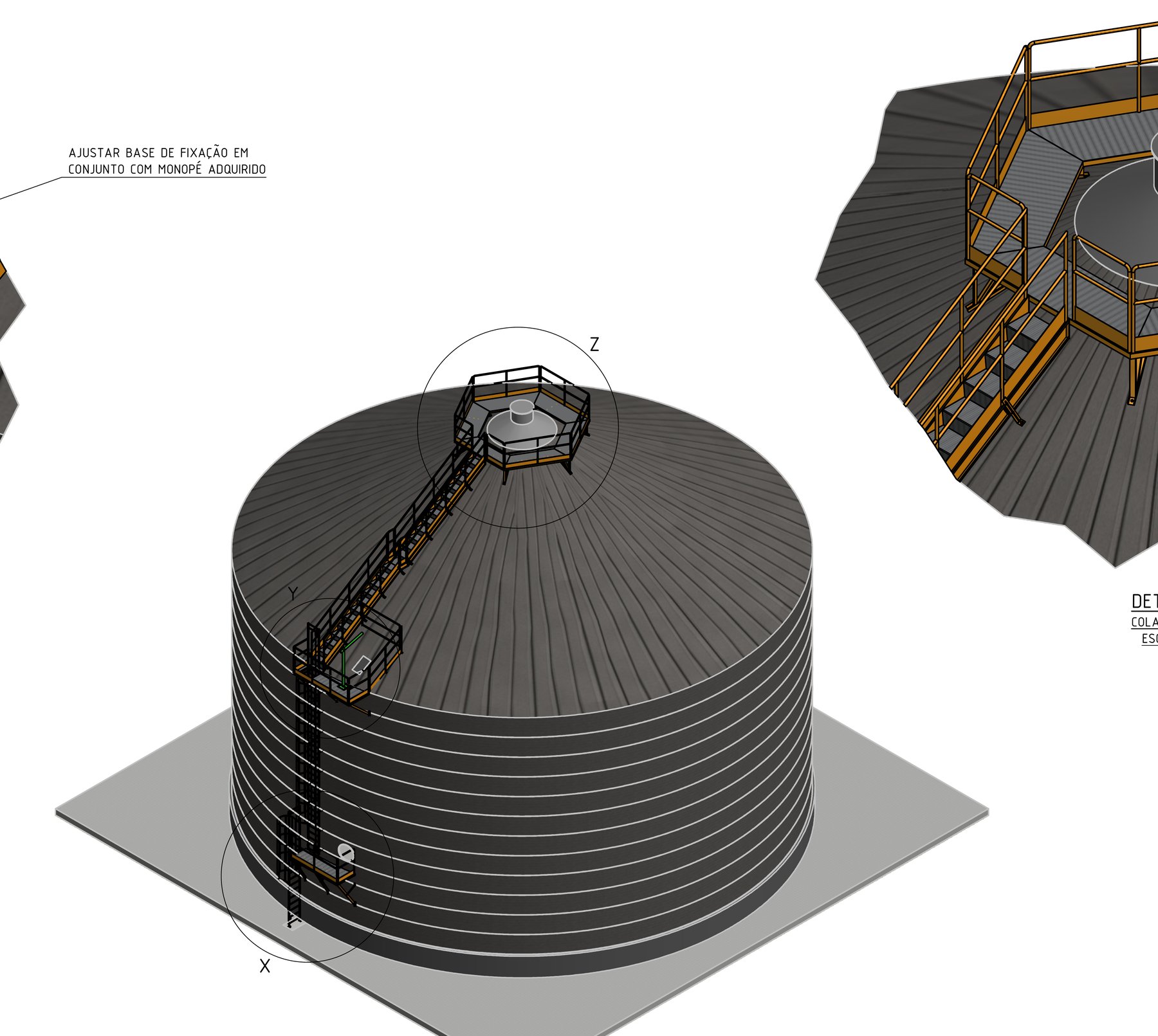
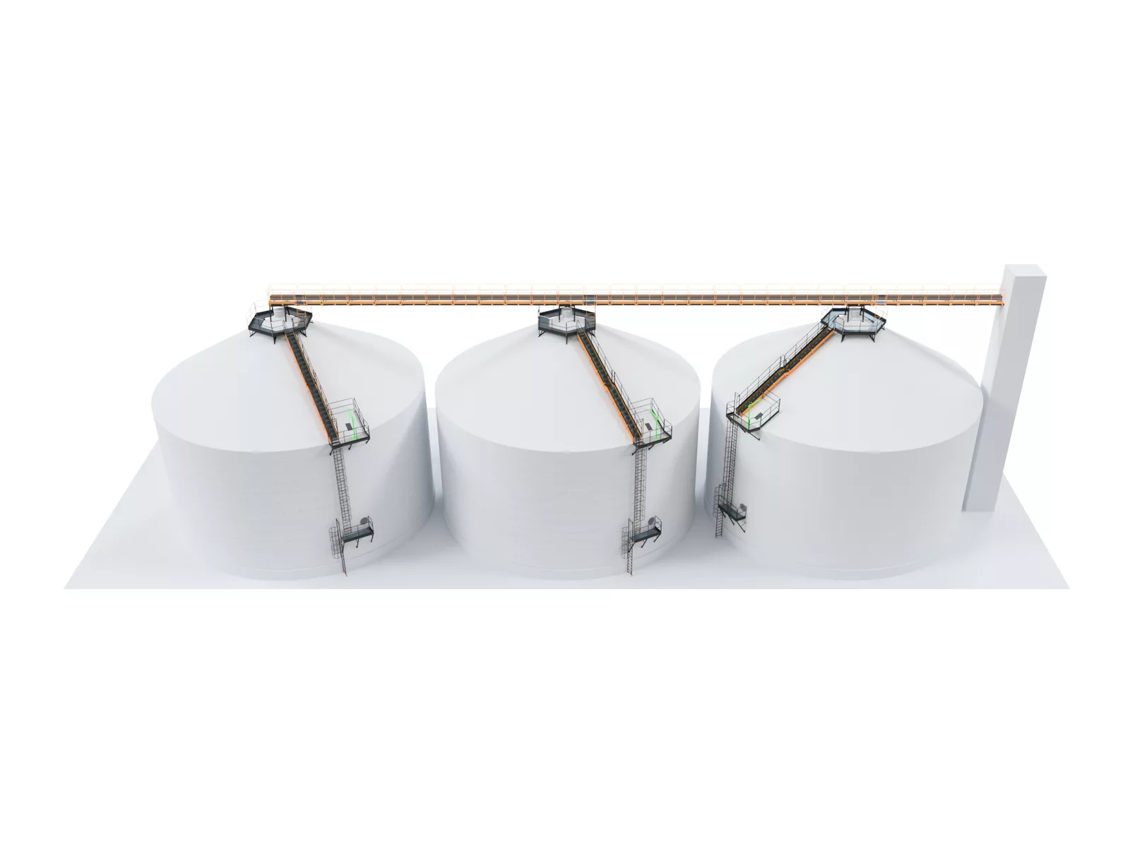
Isometric view of the access assembly shown in the design.
What the design shows
The general view lays out the access route from the lower part of the silo to the top. The assembly includes an initial platform, an intermediate platform, a middle platform and a top collar around the access at the top. The guardrails follow the walkways and enclose the exposed edges.
The drawing also distinguishes new elements from existing components. This distinction is essential for erection because it shows which parts will be fabricated and installed and which parts must be checked before receiving new loads or connections.
The drawing specifies that the mounting base is to be adjusted together with the purchased monopod. It also states that supports are to be modified in the field where they interfere with the existing construction. These notes show that final coordination depends on the dimensional survey and on the inspection of the actual structure.
Platforms and continuity of access
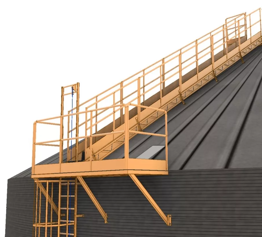
The initial platform must provide a controlled transition between the arrival level and the ladder or the next section of the access. The intermediate platform reduces the continuous climbing length and offers an area for movement and change of position. The middle platform, shown in detail Y, works as a work and access area next to the silo shell.
On each platform, the following must be checked: the flooring, the stiffness of the supports, the stability of the guardrails, the edge protection, the passage between levels and the absence of openings that would allow people or materials to fall. The clear width and the position of the components must remain compatible with the use of the full-body harness, the fall arrester and the other equipment required.
Guardrails are collective protection measures. They reduce the possibility of falling over the edges, but they do not replace the risk analysis or the individual or collective fall protection system specified for sections where there is residual risk.
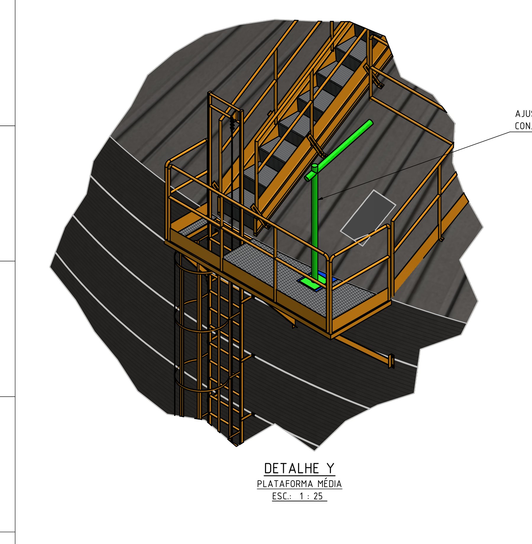
Detail of the middle platform and its integration with the vertical access.
Top access and collar at the top of the silo
Detail Z shows the top collar, installed at the access area to the top of the silo. The purpose of this assembly is to organize the arrival, protect the walkway area and create a safer transition between the vertical access and the top surface.
The top area must be assessed considering the slope and condition of the roof, the presence of nozzles, vents, walkways, process lines, maintenance points and possible slippery surfaces. Access to the roof must not be released only because a ladder exists. The complete route, the connection points, the fall clearance and the emergency plan must be confirmed.
Installation of the collar must preserve the operation of the silo components and must not compromise the weathertightness, the corrosion protection or the integrity of the plates. Any intervention on plates, stiffeners or supports must be detailed and validated by the engineer of record.
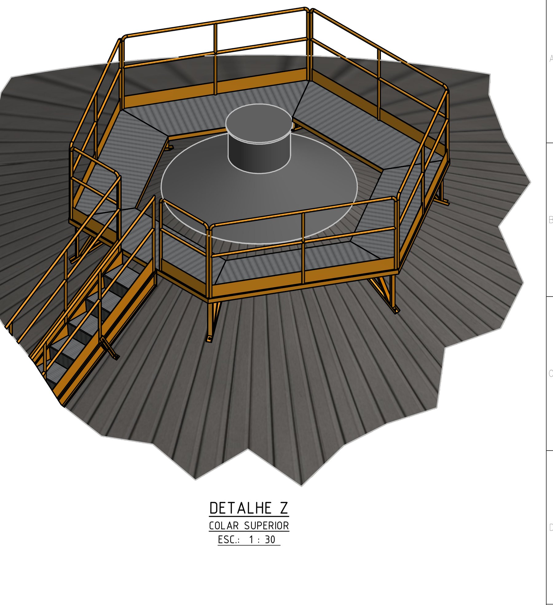
Top collar for organizing access to the top of the silo.
Initial access and modifications to the existing structure
Detail X shows the initial access and the intermediate platform. The geometry of the assembly must be checked against the base, the cylindrical shell of the silo, the existing supports and the area available for erection.
The drawing calls for splicing of existing plates and instructs the removal of existing ladders and accessories. These interventions require planning for isolation, clearing of the area, control of simultaneous work and assessment of the stability of elements that will remain temporarily without support or protection.
The note that calls for modifying in the field the supports that interfere with the existing construction does not authorize uncontrolled changes. Before cutting, welding or relocating a support, the applicable design revision must be confirmed, the condition found must be recorded and the validation of the responsible professional must be obtained. The existing silo structure and the supporting elements must be assessed for their capacity to receive the permanent, variable and accidental actions of the system.
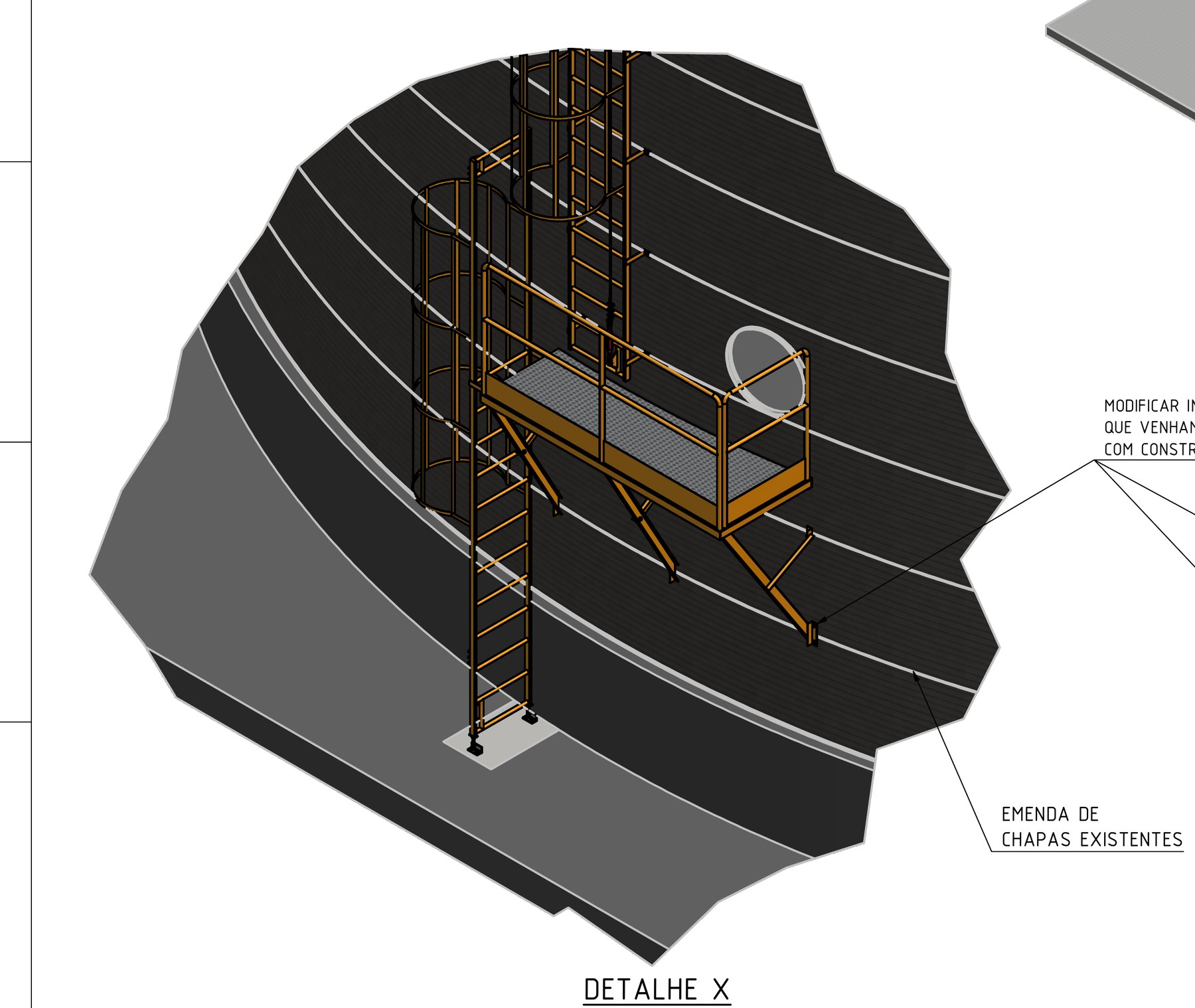
Initial access and intermediate platform shown in the design.
Lifeline: specify, install and use it as a system
The drawing title includes access and lifelines, but the isometric view must be read together with the construction documents, the anchorage details, the manufacturers' instructions and the structural analysis. A lifeline must not be assumed from the existence of a guardrail or a ladder.
Where there is a flexible line, the cable, anchors, intermediate supports, terminations, tensioners and connecting device must form a compatible assembly. The worker must use a full-body harness and the equipment specified for that line. The selection must consider the diameter, the cable construction, the direction of use, the passage through the supports, the sag, the energy absorber and the fall clearance.
The risk analysis must consider the swing-fall effect, the possibility of striking the silo, the passage between platforms, interferences with nozzles and piping, falling tools, access by maintenance crews and rescue on a curved surface or on an elevated roof.
The same concept in silo batteries
At an agro-industrial cooperative in Santa Catarina, CRAVIL, the concept was applied to a battery of steel silos: a top walkway connecting the tops, ladders on the cone of each silo, rest platforms and lifelines along the route. The same design covered the truck tipper elevator, the screens and the truck tarping platform, with access structures and lines sized together.
Inspection and maintenance of the access system
The inspection must cover the silo structure, the spliced plates, the supports, welds, bolts, flooring, guardrails, ladders and the lifeline components. Corrosion, deformations, looseness, cracks, section loss, coating damage, interferences created by new equipment and unrecorded changes must be checked.
The photographs included in the drawing show the general condition of the silos and serve as a visual reference for the intervention. They do not replace the dimensional survey, the field inspection or the structural assessment.
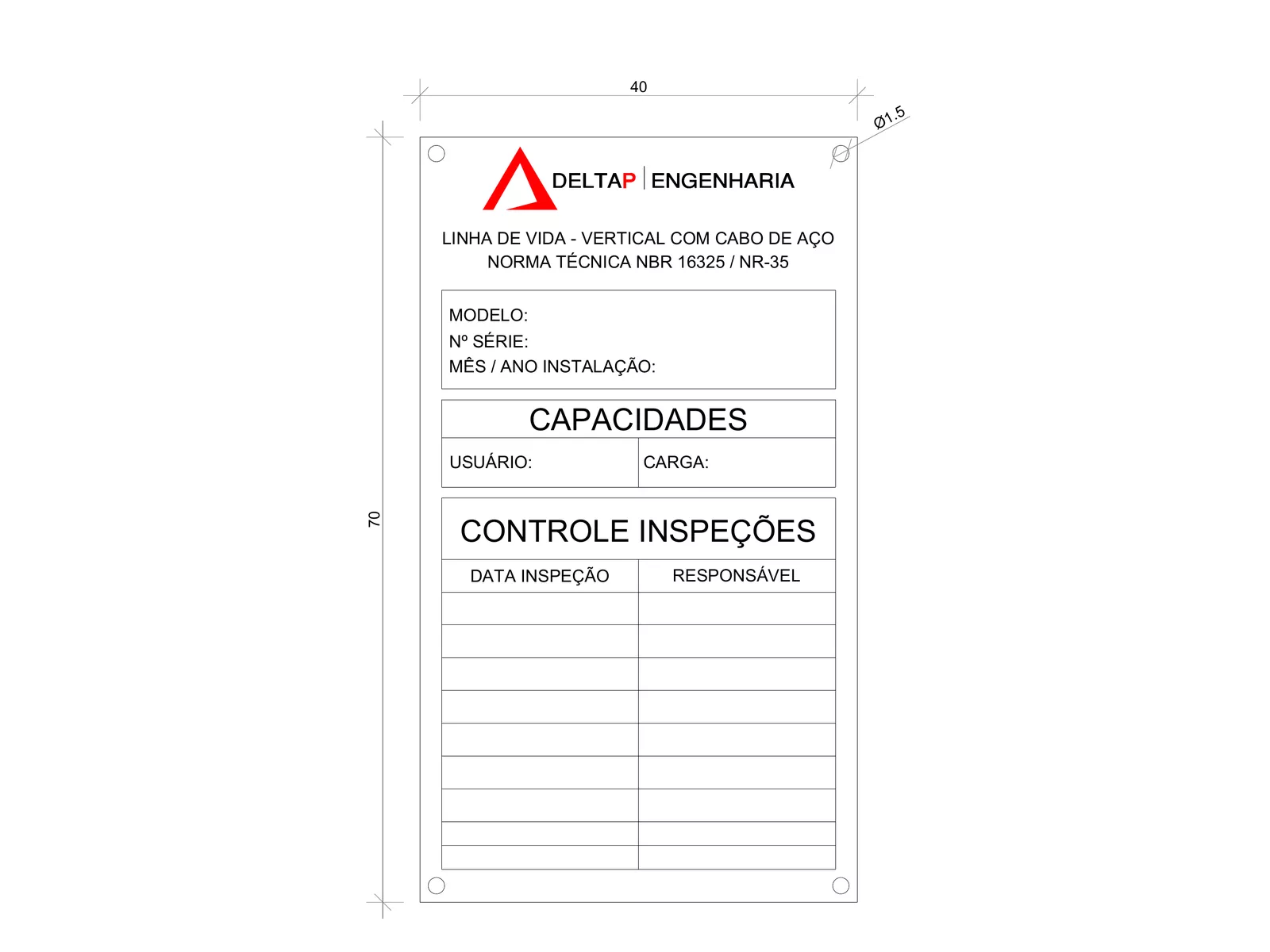
The lifeline must be inspected before use and periodically, at intervals not exceeding 12 months, according to the design, the manufacturer's instructions, the environmental conditions and the organization's safety program. NR-35 requires the risk analysis to consider the selection, inspection, method of use and limitations of the fall protection systems. [1]
Any fall, impact or change that may affect the assembly must lead to removal from service until the system is evaluated by a competent professional. Access must also be closed when there is slippery flooring, significant corrosion, deformation, incomplete guardrail, adverse weather or any other preventing condition identified in the risk analysis.
NR-35 requirements and responsibility for execution
Work at height more than 2.0 m above the lower level, where there is a risk of falling, falls within the scope of NR-35. The organization must ensure risk analysis, prior assessment of site conditions, authorization of workers, training, medical fitness, supervision and emergency planning. [1]
For the designed system, the operating procedure must cover the erection and use of the platforms, climbing and descending the ladders, movement on the top, connection to the protection system, isolation of the silo, falling materials and rescue. Non-routine activities must be assessed for the need of a work permit.
The ABNT NBR 16325 series must be consulted in its current edition for the requirements applicable to anchor devices. The standard does not replace the check of the structure that receives the loads, nor the compatibility between device, personal equipment, design and method of use. [3]
The design excludes from its scope the analysis of existing structures not detailed in the document. The installer is responsible for arranging the necessary checks and interventions, with technical responsibility defined before execution.
Conclusion
DeltaP designs lifelines, anchorage systems, ladders, platforms, guardrails and access upgrades in industrial and agro-industrial facilities. Access and fall protection are handled within the structural design: each solution starts from a survey of the existing structure and checks the elements that receive the loads.
The solution discussed here presents a strategy for improving access to steel silos by combining platforms, ladders, guardrails, top collar and lifelines. The main technical challenge lies in the interface with the existing construction: mounting base, supports, plates, accessories and installed equipment must be coordinated before fabrication and erection.
The solution should only be released after the dimensions are confirmed on site, the supporting structures are validated, the splices and welds are executed under control, the complete system is inspected and the access is integrated into the work-at-height procedure and the rescue plan.
For the full scope, deliverables and design references, see Lifelines and anchorage systems (NR-35). For a quote on upgrading silos, elevators or roofs, send photos and the location through the contact form.
Technical note: this article interprets the drawing provided for informational and technical communication purposes. It does not replace construction design, structural analysis, risk analysis, manufacturers' instructions, inspection by a qualified professional or the mandatory documentation of the installation. Dimensions, capacities, materials and conditions of use must be confirmed on site before execution.
References
Need a technical report or project?
Describe the case and send photos. We return with scope, deadline, and value.
Request quotation