
Caged Ladder and Lifeline for a Truck Tipper Elevator
The technical elements of the caged ladder and lifeline designed for access to the truck tipper elevator, including wire rope, fixings and inspections.
Vertical access to the truck tipper elevator requires integrated protection
This article presents a vertical ladder for access to the truck tipper elevator, designed by DeltaP Engenharia with a safety cage, fixings to the existing cross members of the equipment and a steel wire rope lifeline. The solution was designed to allow access up to the roof, at a height of approximately 8,400 mm, keeping the worker protected from the start to the end of the route.
The ladder, safety cage, supports and lifeline must be used as an integrated system. The safety cage is a collective protection measure against falling sideways and does not replace the fall protection system where there is a risk of falling during the climb, the descent or the transfer onto the roof.
DeltaP prepares designs for access structures, lifelines and anchorage systems for industrial facilities, from the field survey to the specification of each component of the line (wire rope, clips, thimbles and fixing points), compatible with the protective equipment the worker will use. NR-35 requires planning, organization, risk analysis, definition of anchorage systems and anchor points, selection and inspection of equipment, supervision and rescue planning. [1]
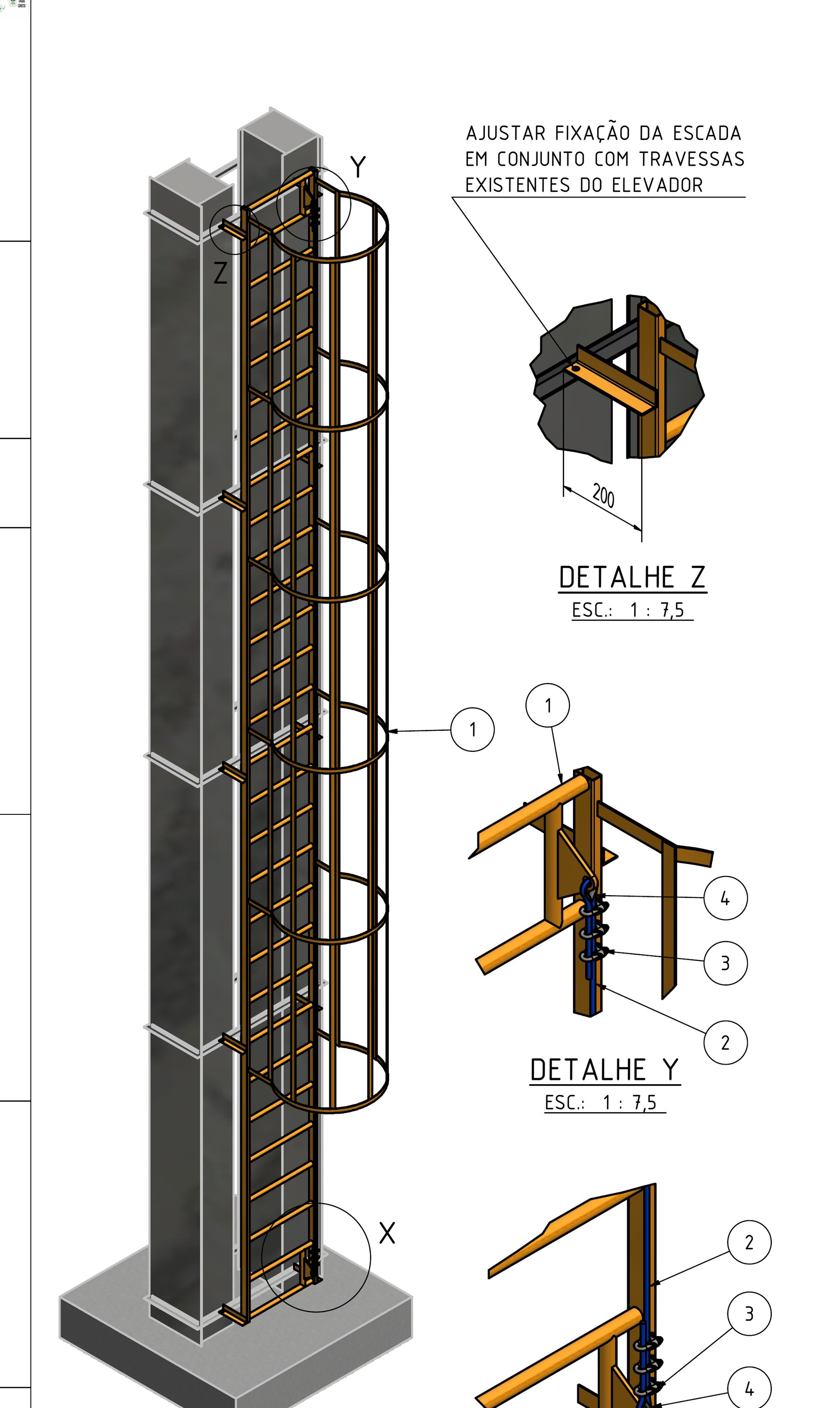
Isometric view of the ladder, the safety cage and the fixing elements of the truck tipper elevator.
Access system layout
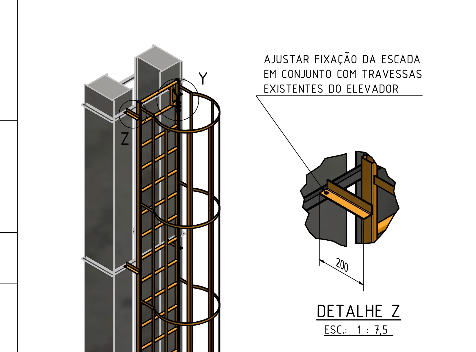
The isometric view shows the ladder installed next to the vertical structure of the elevator. The safety cage follows the protected section along the access and has horizontal hoops distributed over the height. The ladder supports are connected to the existing structure, following the instruction to adjust the fixing together with the elevator cross members.
The design identifies points X, Y and Z to detail the connections and the assembly of the components. The color legend distinguishes the new structure, the existing structure and the lifeline cable. This identification makes checking easier during erection, but it does not replace dimensional control and inspection of the installed parts.
The solution also provides access to the roof. Before release, the transition between the ladder and the roof must be assessed, along with the presence of edges, openings, equipment, sloped or slippery surfaces and the fall clearance available for arresting a possible fall.
Wire rope and specified components
The technical specification lists a length of 3/8” (9.52 mm) galvanized steel wire rope, 6×19, independent wire rope core, 8.5 m long. It also lists six heavy-duty wire rope clips for 3/8” rope and two thimbles for rope of the same diameter.
The presence of these items does not authorize substitutions without validation. The wire rope, clips, thimbles, fixing points, fall arrester and harness must be compatible with one another. The fall protection equipment must be selected to work with the type, diameter and configuration of the specified line.
The specification expressly states that the line must be used with a fall arrester and that a lanyard must not be used to connect the operator directly to the line. This instruction must be included in the operating procedure and communicated to the authorized workers.
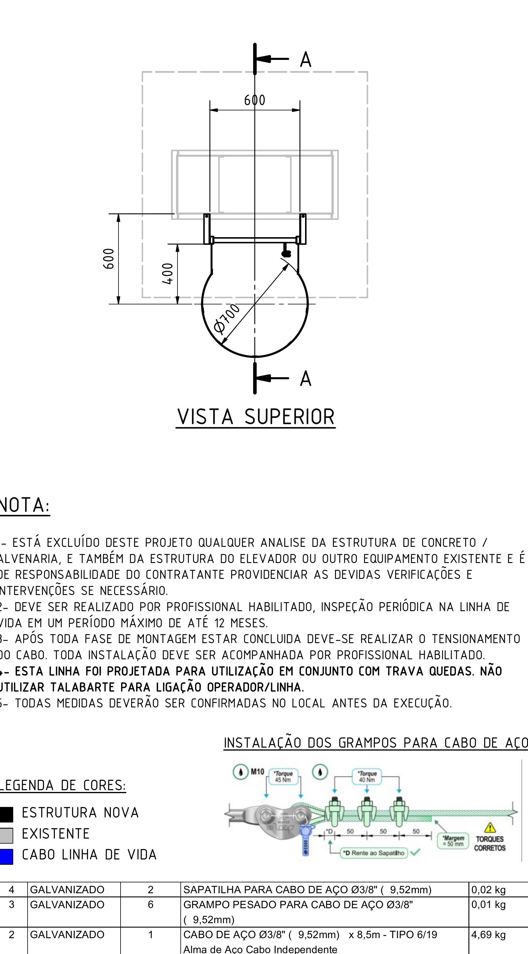
Top view, construction notes, color legend and bill of materials of the design.
Fixing to the existing cross members
Detail Z states that the ladder fixing must be adjusted together with the existing cross members of the elevator. This condition requires a survey of the actual geometry, identification of the available cross members and a check of the capacity of the elements that will receive the loads.
The elevator structure and the other existing equipment are outside the structural analysis covered by the design. The client must arrange the necessary checks and interventions before execution. Cutting, drilling, welding or relocating elevator components without assessment by the engineer responsible for the equipment and the structure is not recommended.
The 200 mm dimension shown in detail Z must be checked against the actual condition. The design dimensions are a reference for fabrication and erection, but must be validated on site before execution, as stated in the technical notes of the design.
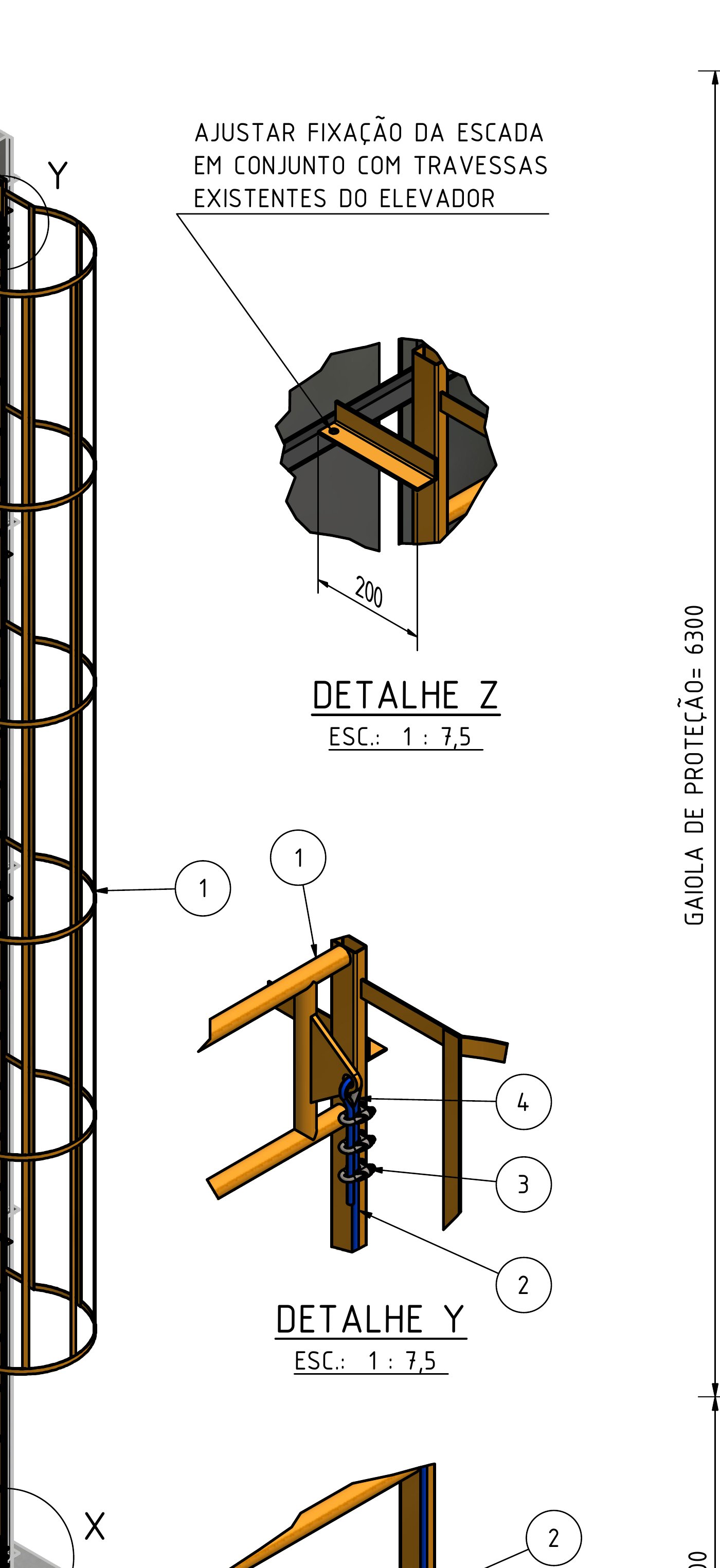
Details X, Y and Z of the fixings and the components associated with the lifeline.
Safety cage and access dimensions
Section A–A shows a safety cage approximately 6,300 mm long and gives the height to the roof as approximately 8,400 mm. The design also gives reference dimensions for the start of the access, including segments of 2,000 mm, 293 mm and 184 mm, which must be checked against the final geometry of the equipment.
The safety cage must remain continuous, stable and free of deformations that reduce the clear passage. Its hoops and verticals must not create entrapment points, interfere with the fall arrester or prevent the connection and safe movement of the worker.
The safety cage does not remove the need to connect to the fall protection system. The worker must use a full-body harness and a fall arrester compatible with the line, from the start of the task until reaching an area that is actually protected. The risk analysis must define the connection and disconnection sequence during the transfer onto the roof.
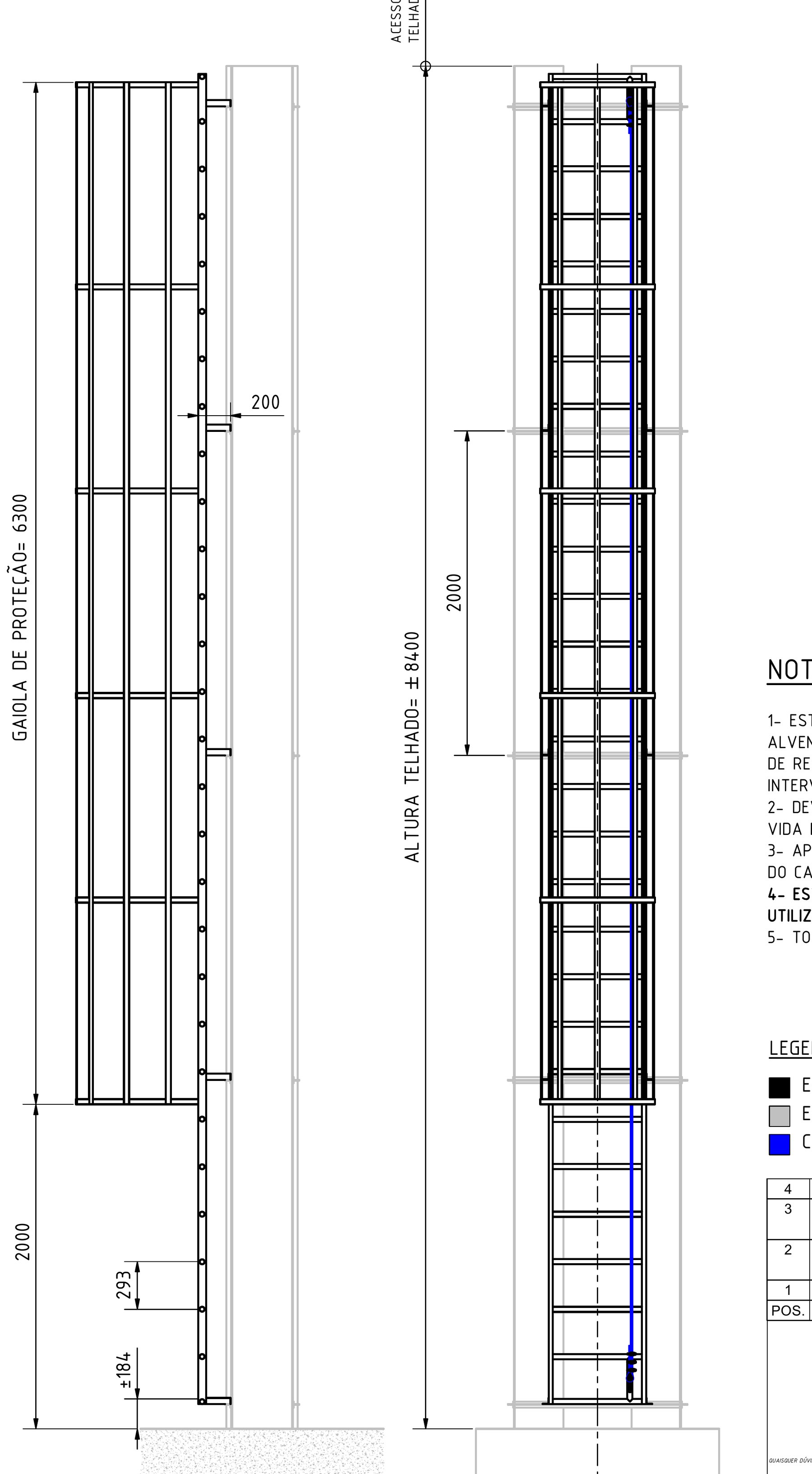
Section A–A and representation of the vertical run of the lifeline cable.
Clip assembly and torque control
The clip installation detail shows the use of a thimble, the arrangement of the clips and reference torques given on the drawing itself. These values must be confirmed with the manufacturer of the model actually supplied and applied with a calibrated tool.
The assembly inspection must check the number of clips, the position of the parts, the seating of the rope in the thimble, the tightening, the absence of crushing or deformation of the rope and the correct orientation of the components. The torque given for a specific model must not be transferred automatically to another component.
After the whole assembly is complete, the specification calls for tensioning the wire rope. Tensioning must be done by a qualified professional or under their responsibility, with the procedure and the final condition of the system recorded.
Inspection and maintenance
The inspection must cover the wire rope over its full length, the terminations, thimbles, clips, ladder supports, safety cage, welds, bolts, the elevator cross members and the transition areas to the roof.
Inspectors must look for broken wires, corrosion, kinks, crushing, core damage, deformations, looseness, cracks, section loss and signs of overload. The elevator structure must be inspected for modifications, vibration, corrosion and interventions that may have affected the fixings.
The specification calls for periodic inspection of the lifeline by a qualified professional at a maximum interval of 12 months. This period must be included in the control program, without excluding inspection before use, after abnormal events and whenever there is doubt about the integrity of the system. Environmental conditions, the manufacturer and the risk analysis may require a higher frequency.
After a fall or significant impact, the system must be removed from service until formally evaluated. The line must not be released based only on an informal visual check or on retightening the clips.
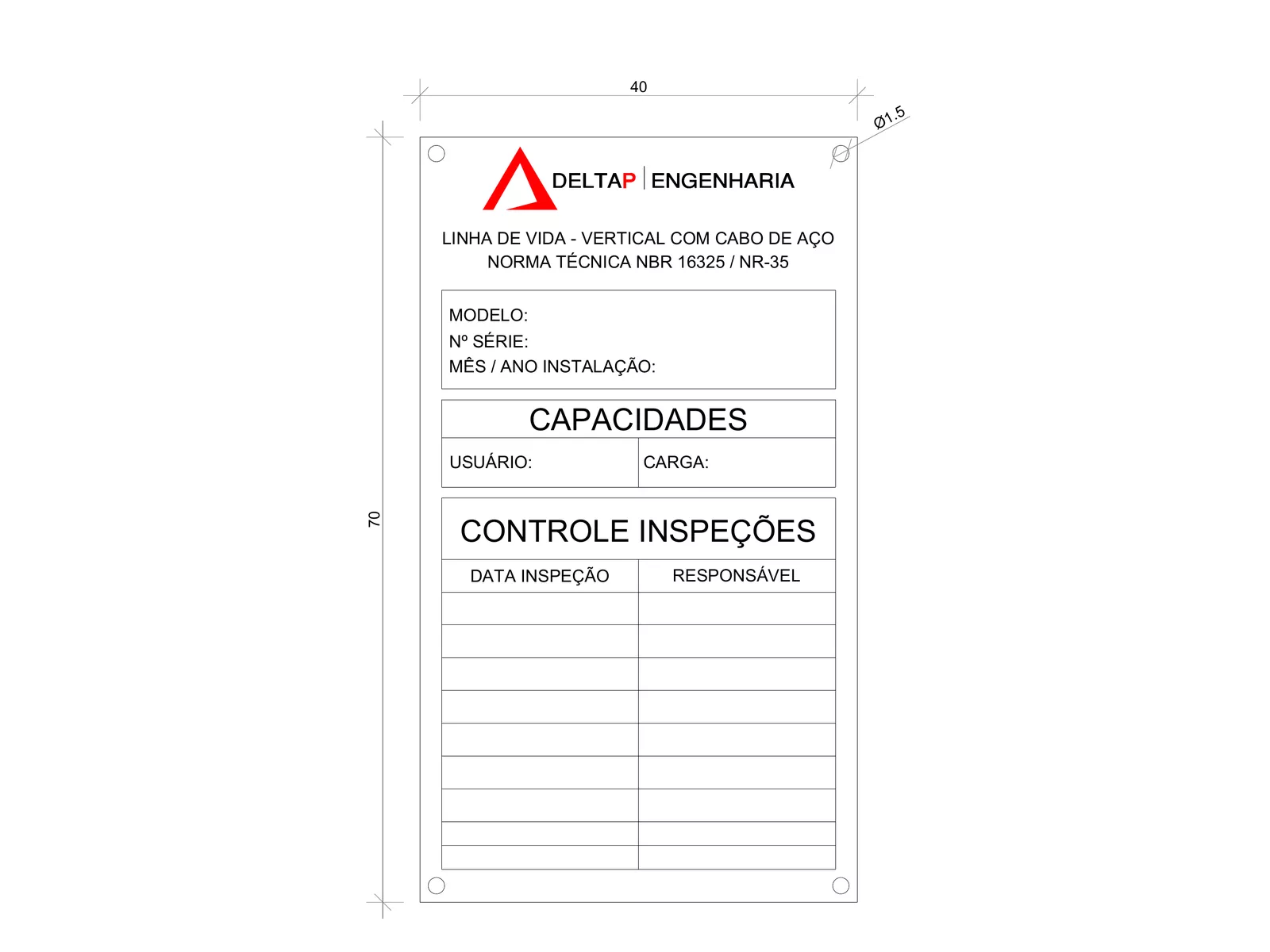
Each vertical lifeline receives an identification tag next to the access point, with the reference standard, capacity, number of users and the inspection control table. Without a completed tag, or with the inspection overdue, the line must not be used.
Requirements for safe use
Access must be made by a worker who is formally authorized, trained and fit for work at height. The procedure must cover isolation of the area, the risk of falling tools, communication, supervision, weather conditions, lockout or control of the equipment where applicable, and the rescue plan.
NR-35 requires the risk analysis to consider the site and its surroundings, the anchorage systems and anchor points, the weather conditions, the selection and inspection of the protection systems, the preventing conditions and emergency situations. [1]
The ABNT NBR 16325 series must be consulted in its current edition for the requirements applicable to anchor devices. The technical standards for the full-body harness, connectors, energy absorbers and fall arresters must also be followed. Compliance does not come from a single component: it depends on the whole formed by structure, line, equipment, installation, use and maintenance. [3]
Conclusion
DeltaP designs access structures, lifelines and anchorages for elevators, truck tippers, silos and other industrial settings. Ladder, safety cage, wire rope, fixings and fall arrester are specified as a single system, with field survey, detailing of the fixings, specification of the components and, when contracted, follow-up of the installation and inspection for release.
The solution discussed here presents a vertical access layout for the truck tipper elevator with ladder, safety cage and an 8.5 m galvanized steel wire rope lifeline. The critical execution points are the fixing to the existing cross members, the compatibility of the fall arrester, the correct assembly of the clips, the final tensioning and the safe transfer onto the roof.
The installation should only be released after the dimensions are confirmed on site, the elevator structure is assessed, the work is carried out by competent professionals, the inspection is documented and the system is integrated into the work-at-height procedure and the rescue plan.
Other vertical and horizontal access
At the same agro-industrial facility, the design included lifelines for the screens, the steel silos and the truck tarping platform, where the worker moves over the load while attached to a horizontal line carried by portal frames.
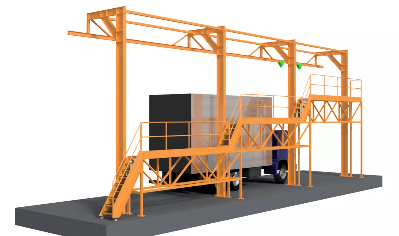
The scope, deliverables and references for this type of design are in Lifelines and anchorage systems (NR-35). For a quote, send photos of the equipment and the access height through the contact form.
Technical note: this article interprets the drawing provided for informational and technical communication purposes. It does not replace construction design, structural analysis, risk analysis, manufacturers' instructions, inspection by a qualified professional or the mandatory documentation of the installation. Dimensions, capacities, materials, torques and conditions of use must be confirmed on site and in the official documentation before execution.
References
Need a technical report or project?
Describe the case and send photos. We return with scope, deadline, and value.
Request quotation