
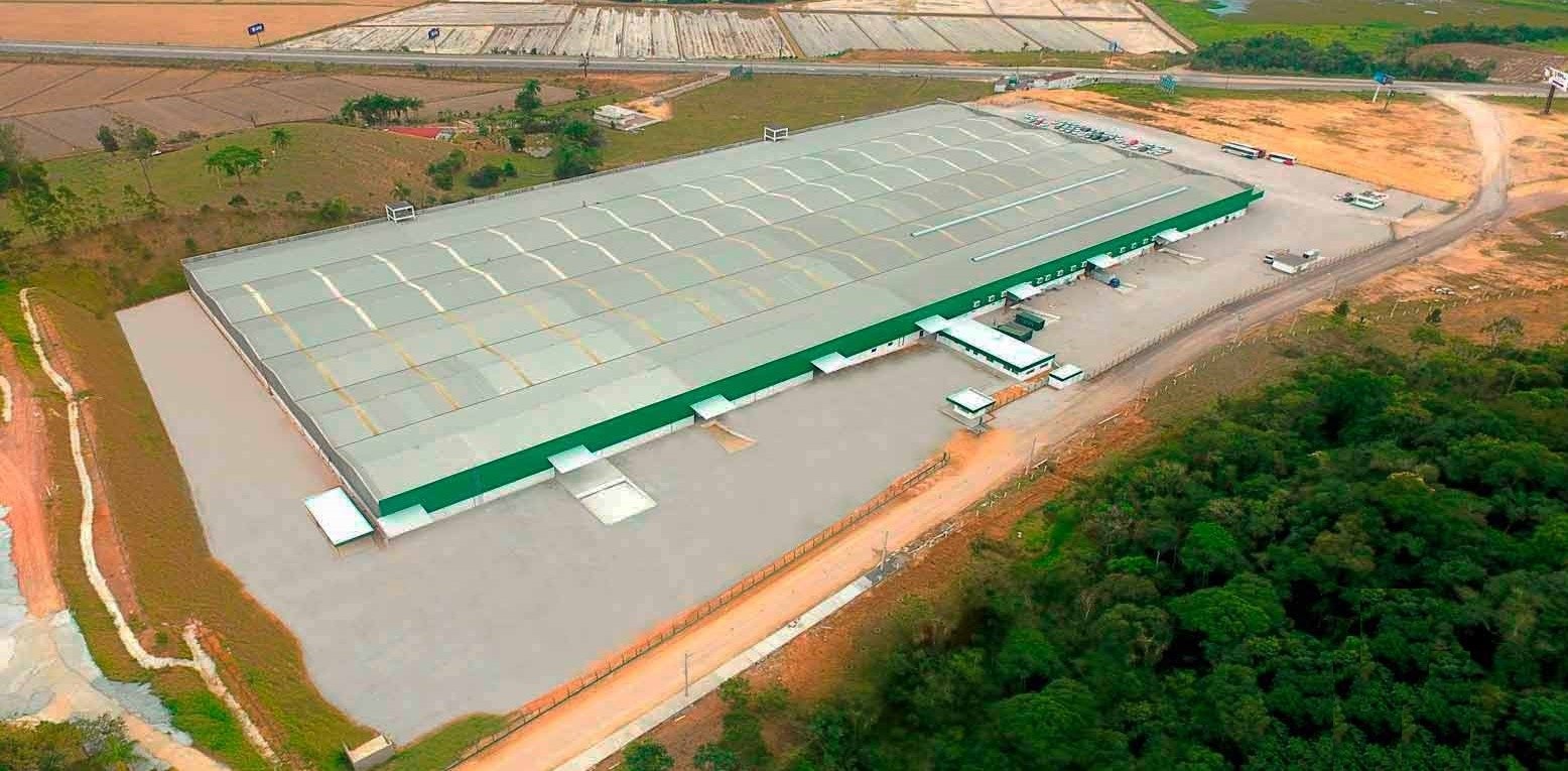
Diagnosis and Retrofit of Steel Structures: the Case of a 30,600 m² Large Warehouse Complex
How DeltaP applies an inspection, diagnosis and structural retrofit method to a 30,600 m² industrial complex, from the site inspection to the strengthening design.
Large industrial and logistics assets share a recurring problem: decisions on maintenance, strengthening or change of use depend on information that is rarely up to date. The original design seldom reflects decades of operation, one-off modifications and the actual wear of the materials. Owners, asset managers and expansion directors need to assess these assets without stopping operations and without deciding on assumptions.
DeltaP Engenharia works at this point as a technical diagnosis partner, following a six-stage work method: inspect, diagnose, analyze, design, intervene and monitor. The case below describes how this method was applied to an industrial complex with a total area of 30,600 m², and shows how a well-planned field survey turns into an engineering decision.
Inspect: dimensional survey of a large complex
Any structural assessment starts from exact knowledge of the existing geometry. The complex measures 120 meters wide by 255 meters long, split into two blocks: 120 meters in length in Building A and 135 meters in Building B.
To survey this volume without stopping the client's operation, the site inspection was planned by sectors. The complex was divided into 14 technical zones (Stages A to N), which allowed each module to be inspected separately and in sequence:
| Block | Total area | Composition |
|---|---|---|
| Block A | 14,400 m² | 1 head-end zone (Stage B, 2,400 m²) + 6 modules of 2,000 m² (Stages A, C, D, E, F, G) |
| Block B | 16,200 m² | 1 base zone (Stage J, 2,400 m²) + 6 modules of 2,300 m² (Stages H, I, K, L, M, N) |
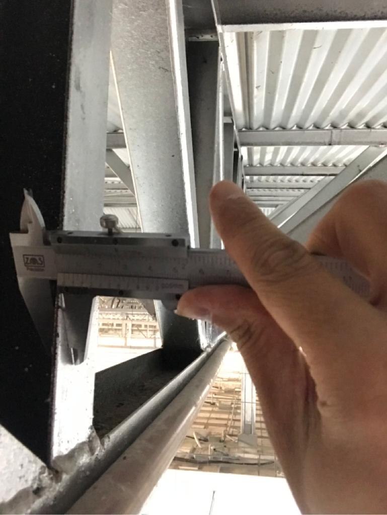
The survey combined two scales of work. At the macro scale, drones and photogrammetry covered the roof area and the gutter system, identifying geometric deformations, debris buildup and spots of surface oxidation without exposing crews to unnecessary work at height. At the micro scale, precision calipers measured the actual thickness of connection plates and sections, identifying, for example, nominal thicknesses of about 6.3 mm (the standard corresponding to 1/4 inch). This direct measurement is what makes it possible to identify section loss from corrosion, something no original design documents.
Diagnose: reading connections and deformations
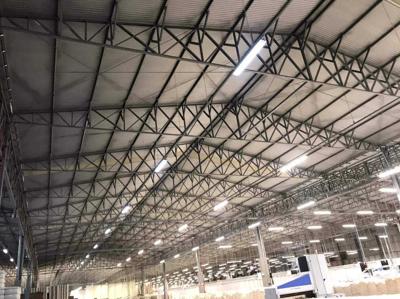
With the field data in hand, the diagnosis turns measurements into performance indicators. The steel roof trusses that carry the roof of the complex, spaced every 5 meters, were evaluated for acting loads and actual deformations (deflections), comparing the observed behavior with the behavior predicted in the design.
The inspection of connections and welds established the physical condition of the critical connection points, while the mapping of defects documented the local mechanical behavior under self-weight and climatic actions.
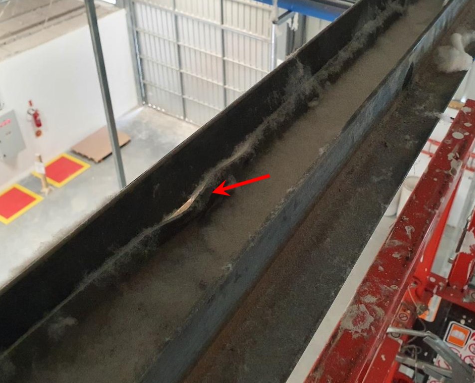
This cross-check between geometry, residual thickness and observed behavior is what supports the decisions in the next stage.
Design: retrofit and new suspended loads
Much of the demand for structural diagnosis comes from the need for a retrofit: adapting an existing industrial building to a new operation. In this case, the roof trusses already carried a dense network of suspended services: fire protection piping with sprinklers, large cable trays, HVAC ducts and lighting systems distributed along the clear spans.
To make a new use possible without compromising the structure, DeltaP rebuilt the original calculation model from field data (15-meter column spacing and the actual truss detailing), recalculating:
- the residual load capacity of the bottom and top chords of the roof trusses;
- the technical feasibility of anchoring new suspended services;
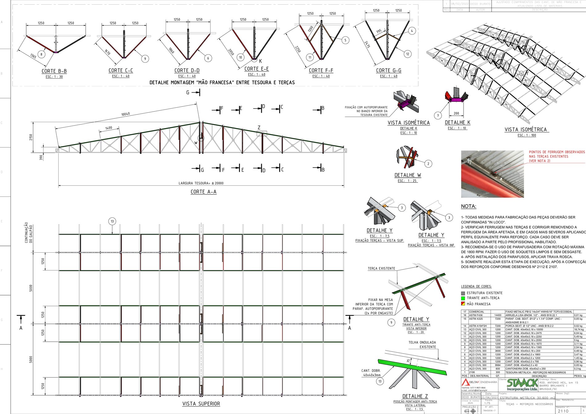
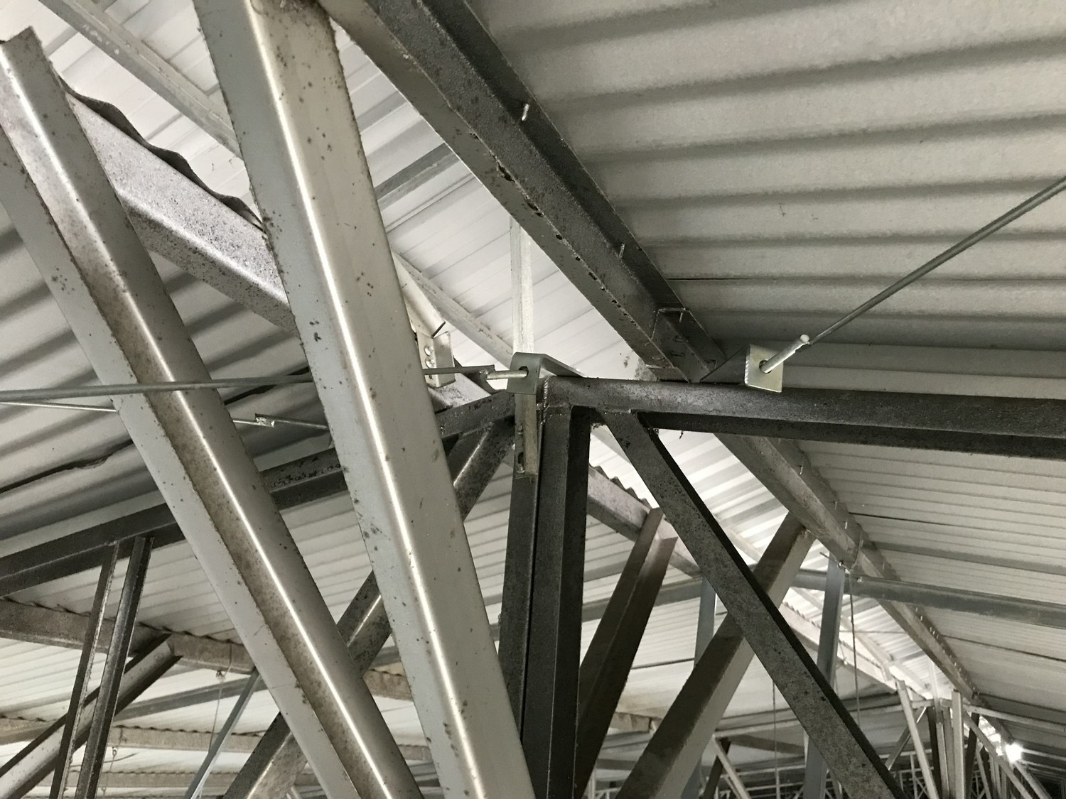
- the structural strengthening points required at the truss panel points.
This last item is what sets a well-calibrated retrofit design apart: instead of proposing widespread replacement of sections, the calculation locates exactly where strengthening is needed, keeping the existing steel where the structure still has available capacity.
The building operates as a textile distribution center, with large volumes of fabric and bales stored under the strengthened roof itself. This high fire load made field welding a risky option. Given this scenario, the strengthening design was developed for fully bolted assembly: sections and plates fixed with self-drilling screws, with no welding carried out inside the operating building.
Intervene and monitor: controlled, traceable execution
Once the design is approved, the intervention phase requires the same rigor as the diagnosis stage. DeltaP follows the execution with continuous dimensional inspection on site, checking that each new element (plate, bracing, stiffener) is installed with the thickness calculated in the design.
The same sectorization used in the survey guides the phased execution: the erection crews work separately on one module at a time, with aerial work platforms positioned at the roof, while the neighboring modules keep operating normally.
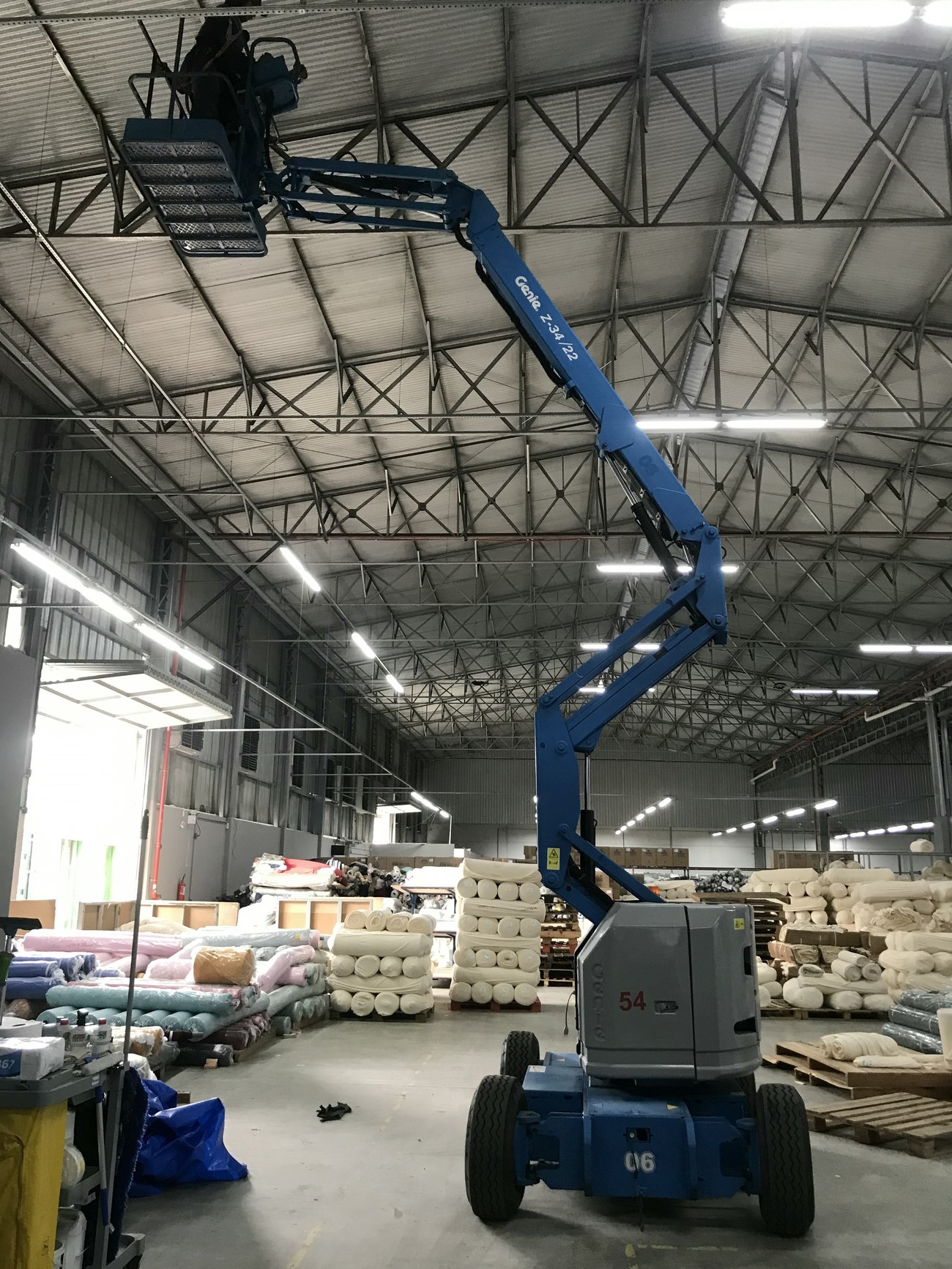
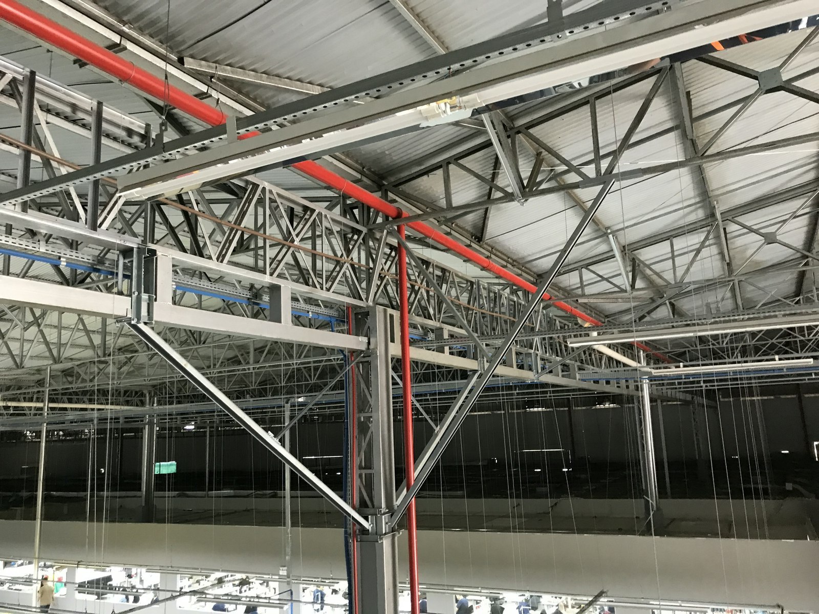
At the end, the post-intervention as-built consolidates all field changes into a single technical record file, a document that becomes the reference for future audits, insurance and regulatory approvals of the asset.
The same method in smaller structures
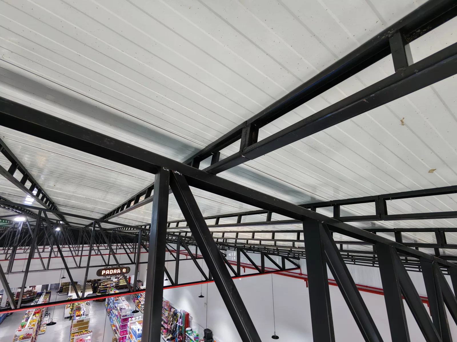
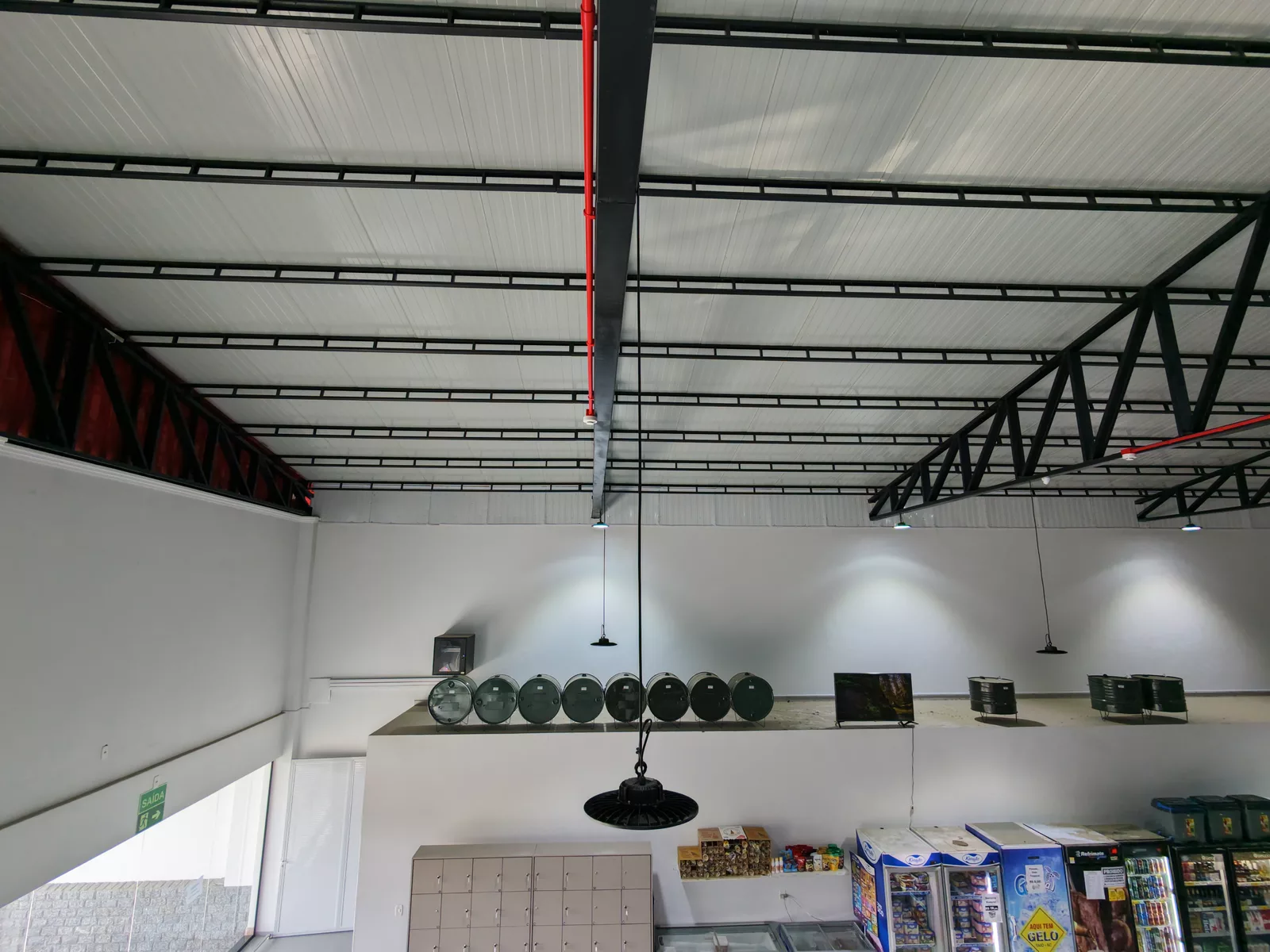
The inspection procedure used in the 30,600 m² complex is the same one we apply to commercial buildings and small roofs. In a recent site inspection of a retail store, the survey found purlins bearing off the truss panel points and a bottom chord without enough lateral bracing, two conditions that reduce the capacity of the roof without giving any visible sign until the problem has progressed.
Conclusion
A survey by sectors, precision measurements and a calculation model rebuilt from field data make it possible to decide on maintenance, strengthening or change of use based on the actual condition of the structure. In the 30,600 m² complex, the result was a localized, bolted strengthening, executed module by module with the operation running, and a technical record file that becomes the reference for audits and insurance.
How to commission a diagnosis
The scope, stages and deliverables of the service are described in Diagnostic engineering for steel structures. For a quote, send general photos and photos of the areas of concern, the approximate area and the reason for the assessment through the contact form. When the diagnosis calls for strengthening, the same team designs the solution and can follow the installation through technical construction management.
Need a technical report or project?
Describe the case and send photos. We return with scope, deadline, and value.
Request quotation